RM06J153CT 0603 SMD Resistor Datasheet & Specs Deep Dive
The RM06J153CT is a representative 15 kΩ part in the 0603 SMD family, frequently chosen for space-constrained, medium-volume PCBs. This guide uses datasheet-driven checks so engineers can quickly verify suitability for pull networks, filters and bias lines. It highlights key electrical, mechanical and procurement items to confirm before design or purchase.
Readers will find concise decoding of the part number, which datasheet tables to read, practical calculations for power and RC timing, footprint and reflow notes, and a short incoming inspection checklist to use during procurement.
Product overview & part-number decoding (background)
What the part number means
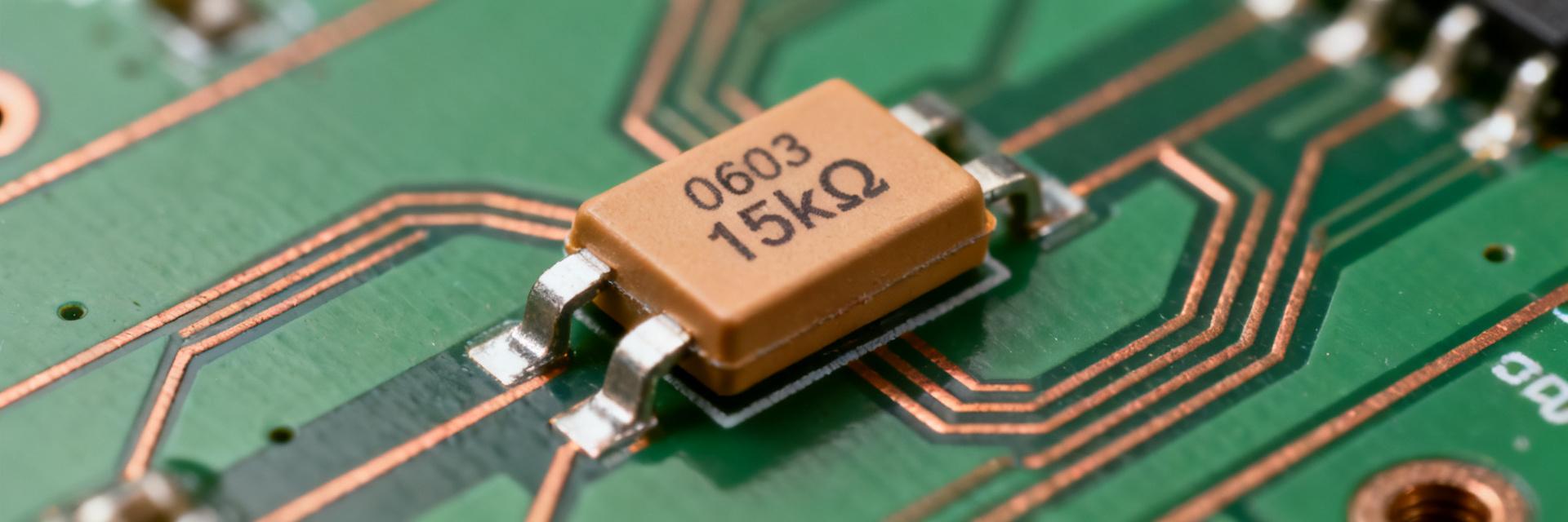
Point: RM06J153CT encodes family, value and ordering options. Evidence: the datasheet ordering table typically lists size code (RM06 → 0603 family), value code (153 → 15 kΩ), tolerance letter (e.g., J → ±5%/±1% depending on vendor) and packing/termination code (CT → tape-and-reel variant). Explanation: confirm exact letter meanings on the manufacturer datasheet’s ordering codes table before ordering to avoid mismatched tolerance or reel options.
| Code Segment | Nomenclature Meaning | Parameter Value / Detail |
|---|---|---|
| RM06 | Package Size Code | 0603 Metric (1608) Standard Footprint |
| J | Tolerance Code | ±5% (Standard Thick Film Range) |
| 153 | Resistance Code (3-digit) | 15 x 10³ = 15,000 Ω (15 kΩ) |
| CT | Packaging / Tape Code | Paper Tape & Reel Carrier |
Typical applications for a 15 kΩ 0603 resistor
Point: 15 kΩ in 0603 is common for pull-ups/pull-downs, RC timing and bias networks. Evidence: typical datasheets list rated power and TCR so designers can confirm circuit fit. Explanation: use a “15 kΩ 0603 resistor for pull-up” when the expected steady current and dissipation are minimal; re-evaluate if tolerance or temperature drift (TCR) will shift thresholds in sensitive analog or precision ADC inputs.
Key datasheet specifications explained (data analysis)
Electrical parameters to extract and why they matter
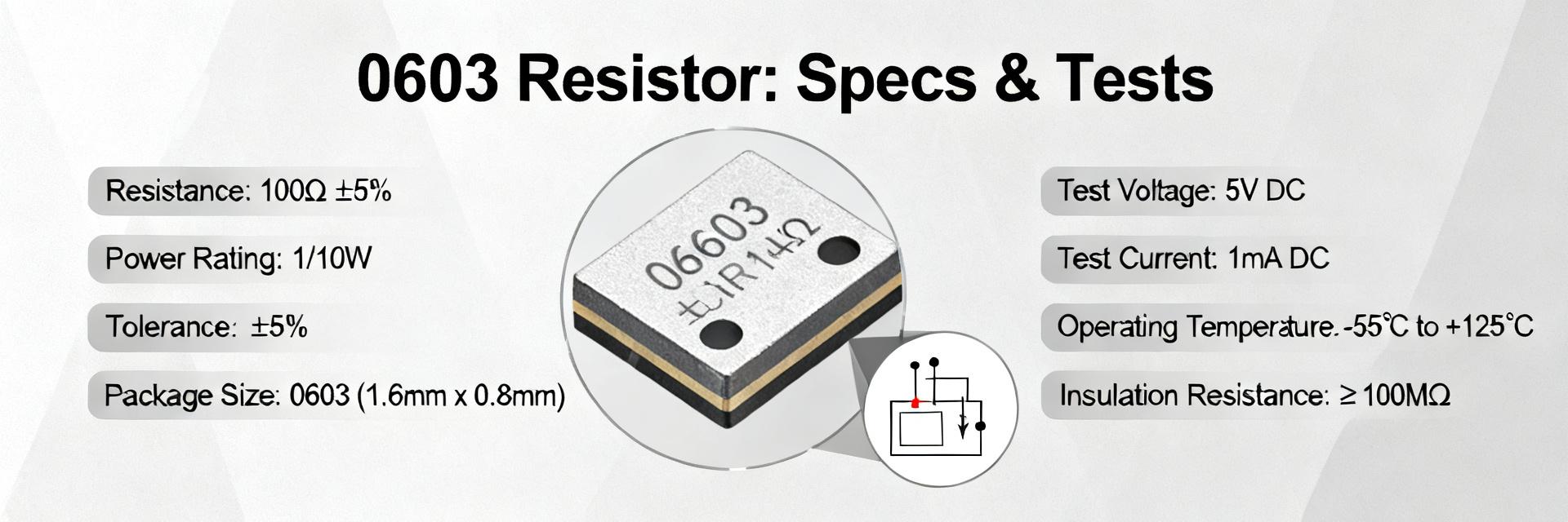
Point: extract resistance, tolerance, TCR, rated power, max working voltage and noise from the datasheet. Evidence: the datasheet electrical table shows nominal value and limits. Explanation: tolerance defines initial accuracy; TCR (ppm/°C) predicts drift with temperature; rated power (typical 0.1 W for 0603 family) and max voltage set safe operating limits; compare numeric values to your worst-case environment to confirm margins.
Physical & packaging specs
Point: check nominal dimensions, termination finish and tape-and-reel packing codes. Evidence: datasheets include Mechanical Dimensions and Packaging Information figures. Explanation: 0603 nominally measures ≈1.6 mm × 0.8 mm; termination finish (lead-free tin, Ni barrier, etc.) affects solderability and reliability; reel quantity and code (CT style) determine assembly readiness and procurement acceptance.
| Standard Parameter | Value Limit (0603 Family typical) | Critical Design Context |
|---|---|---|
| Nominal Resistance | 15 kΩ | Baseline value for circuit equations |
| Power Rating at 70°C | 0.1 W (1/10 W) | Thermal limit before derating curves apply |
| Max Working Voltage | 70 V to 100 V (Vendor dependent) | Must exceed worst-case circuit rail transient |
| T.C.R. (Temp Coefficient) | ±200 ppm/°C (Typical for Thick Film) | Quantifies resistance drift over temperature |
| Dimensions (L × W × T) | 1.60 × 0.80 × 0.45 mm | Establishes footprint layout and stencil design |
Electrical performance & reliability data (data analysis)
Thermal behavior and derating
Point: use power vs. ambient curves to derate continuous loading. Evidence: the datasheet typically provides a power-vs-temperature chart. Explanation and example: for a 15 kΩ pull-up at 3.3 V, I = 3.3/15,000 = 0.22 mA and P = V^2/R = 0.000726 W (0.73 mW), well below a ~0.1 W 0603 rating. If the curve shows 60% allowed power at 70°C, allowed P = 0.1 W × 0.6 = 0.06 W — still ample margin for this pull-up.
RC Timing & Filter Reference Calculation
When pairing the RM06J153CT (15 kΩ) with a standard 10 nF capacitor for filter networks:
      Time Constant (τ) = R × C = 15,000 Ω × 10 × 10⁻⁹ F = 150 µs

      Cutoff Frequency (fc) = 1 / (2πRC) ≈ 1.06 kHz
Note: Always factor in the ±5% resistor tolerance and capacitor tolerances when building precision analog filters or timing loops.
Reliability and qualification tests
Point: check solderability, thermal shock, moisture resistance, load life and overload tests. Evidence: datasheet reliability table lists test methods and acceptance criteria (resistance change limits). Explanation: acceptable change is often within specified % (e.g., ±1% or ±0.5%) after stress; flag missing life or solderability data for procurement QA, since production yields and long-term drift depend on these qualifications.
PCB footprint, assembly & soldering best practices (method guide)
Recommended land pattern and footprint tips
Point: follow manufacturer or IPC land patterns for pad geometry and solder fillet expectations. Evidence: datasheets or IPC tables provide pad recommendations. Explanation: for 0603, use pads sized to promote reliable fillets (pad length roughly half to two-thirds of component body), maintain paste aperture ~60–80% of pad area, include courtyard/clearance and consider thermal relief or nearby vias when higher dissipation is expected to help heat spreading during reflow.
Reflow profile and handling
Point: apply lead-free reflow recommended profile and ESD handling. Evidence: many datasheets include a recommended reflow graph. Explanation: follow vendor peak temp guidance (typical lead-free peaks ~245–260°C) and soak profiles; common mistakes include over-stenciling paste, insufficient fillet, and tombstoning due to paste imbalance—remedies: adjust aperture, inspect paste transfer and balance pad land patterns.
Application examples & selection guide (case study / method)
Reference circuit examples using a 15 kΩ 0603 resistor
Point: illustrate pull-up and RC filter uses. Evidence: compute from basic circuit formulas. Explanation: (1) Pull-up to 3.3 V → I = 0.22 mA, P = 0.73 mW; safe vs a 0.1 W rating. (2) RC filter with R=15 kΩ and C=10 nF → τ = R·C = 150 μs, fc = 1/(2πRC) ≈ 1.06 kHz. Account for tolerance and TCR when timing or threshold precision matters.
Substitution, equivalents and cross-checking
Point: match value, tolerance, TCR, power, finish and reliability class when substituting. Evidence: cross-reference requires matching electrical and packaging specs on datasheets. Explanation: do not accept a substitute solely by nominal resistance; verify board footprint compatibility, termination finish and test results listed on the datasheet, and confirm reel code if automated placement is used.
Sourcing, procurement & incoming-inspection checklist (action suggestions)
Ordering information & packaging codes
Point: verify full ordering code and packaging before PO. Evidence: datasheet ordering table maps suffix letters to packing and finish. Explanation: include exact PN, value code, tolerance, termination finish, reel quantity and lot code on the PO; note RoHS/lead-free statements and storage/shipping recommendations to prevent moisture or handling issues.
Incoming test & QA checks
Point: perform visual, electrical and sample life checks on receipt. Evidence: typical QA procedures reference DC resistance checks, solderability and sample load testing. Explanation: carry out visual inspection, sample DC resistance vs nominal, solderability test on representative reels and retain date-code traceability. For critical runs, define AQL/sample sizes and store reels in ESD-safe, controlled humidity conditions.
Summary
- RM06J153CT is a 15 kΩ part in the 0603 family; confirm rated power, tolerance and TCR from the datasheet before design to ensure thermal and accuracy margins.
- Verify mechanical and packaging tables for dimensions, termination finish and reel codes to avoid assembly or procurement mismatches; follow recommended land patterns for reliable solder fillets.
- Use simple calculations (P=V²/R, τ=R·C) and power-vs-temperature derating curves from the datasheet to validate continuous loading; implement a brief incoming QA plan for production acceptance.
Common questions
How do I calculate power dissipation for a 15 kΩ pull-up?
Compute current I = V/R and power P = V²/R. For 3.3 V with 15 kΩ, I ≈ 0.22 mA and P ≈ 0.73 mW. Compare this to the part’s rated power and the datasheet derating curve to ensure adequate margin at your PCB ambient temperature.
What footprint checks should I perform for a 0603 resistor?
Confirm the mechanical dimensions from the datasheet, use the recommended pad geometry or IPC land pattern, set paste aperture to ~60–80% of pad area, and verify courtyard/clearance. Check stencil and placement machine settings to avoid tombstoning and ensure consistent solder fillets.
Which incoming tests are most valuable for small SMD resistors?
Perform visual inspection for physical damage, sample DC resistance measurements against tolerance, solderability checks on representative reels and date-code traceability. For mission-critical production, add sample load life testing and retain documentation for lot acceptance and warranty traceability.
What is the meaning of the RM06J153CT part number code?
The part number decodes as: RM06 represents the 0603 size family; J denotes a ±5% resistance tolerance; 153 encodes the 15 kΩ nominal resistance (15 followed by 3 zeros); and CT specifies the tape-and-reel packaging option.